A machine tools which is used for producing flat or profiled surface, grooves or slots with the help of revolving multiple tooth cutter is known as milling machine. Milling machine occupies a place opposite to lathe.
Principle
SPECIFICATIONS
Milling machine size is defined by the dimension of its table i.e. length and breadth. Other main specification of this machine is horse power of the motor, speed of the spindle, feed and the drives.TYPES OF MILLING MACHINES
Milling machines are being made of numerous sizes and types. They are classified as under:Column and Knee type milling:
Work table is supported on knee like casting which can slide in vertical direction along vertical column. The table can travel longitudinally and cross-wise. It can be moved up and down. It is of three types:
a. Horizontal milling machine
b. Vertical milling machine
c. Universal milling machine
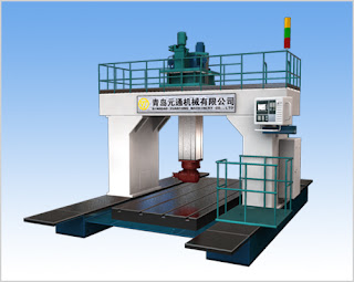
Planar milling machine:
This is high production machine jobs. It is similar to double housing planar. In the planar tool post spindle carries are mounted which are operated by individual motors. In addition to horizontal milling heads are fitted on a cross rail. The other two types are:
a. Fixed bed milling machine
b. Special types of milling machines
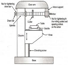
PARTS OF PLAIN MILLING MACHINE
Base and Column:
Base is a main casting of the machine. The hollow base serves a tank for cutting fluid. The electric motor that drives the machine spindle and charge gears for the power feed is generally housed in lower part of column. The top holds over arm and also contains spindle and change gears.
Knee:
It is raised or lowered with elevating screw to adjust the height of the work pieces. After adjusting the knee to the required height it is clamped in position so that it does not shift while machine is in operation.Saddle:
It is mounted on the top of the knee. It is adjustable on ways on top of the knee.Table:
It is the rectangular casting that is supported on top of the saddle. It possesses T-slots running the full length of its top to provide T-bolts for work holding devices. It is fed longitudinally by power drive or hand wheel drive. The table may also be clamped in position during cutting operation to provide rigidity.Over ram:
Over ram that extends outwards at the front of the machine. It is generally rectangular in section. To support arbor properly over ram can be moved in or out to the required length. The braces from the table often support the over ram especially during heavy cuts.Spindle:
It is placed in bearing inside the column. Its outer end just projects from the column face and is provided with tapered holes and driving keys for locating and driving cutters. End mill cutters are directly inserted in the spindle, other cutters have to be mounted on the arbour.MILLING METHODS
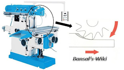
Conventional milling:
This form of milling is also known as Up-milling. Here the work is fed against the rotation of the cutter. So more clamping forces are required to hold the work-piece. It has tendency to lift the job upwards. Due to all these functions its practicable and also provides better surface finish.
Climb milling:
This form of milling is also known as Down-milling. Here the work is fed in the direction of rotation of the cutter. So less clamping forces are required to hold the work-piece. It has no tendency to lift the job in any direction. Due to all these functions its impracticable and also provides surface free from back lash error.


A group of highly dedicated and experienced employees form a dynamic team, The manufacture of Gear Cutting Tools, Broaches and Allied Products.
ReplyDeleteSpline Gauges
cnc milling machine It is imperative that we read thread post very carefully. I am already done it and find that this post is really amazing
ReplyDeleteThe machine crossrail is only necessary for portal machine design, it is to connect the 2 machine columns to make it a portal milling machine, or also known as gantry milling machine. cnc milling
ReplyDeleteThis is really very helpful information. I appreciate it, thanks for share it. Get more details about Milling Machines Manufacturer
ReplyDeleteSuch an informative post. I was finding more information about Universal Milling Machine Manufacturer, then i found this post. Keep posting this kind of helpful data.
ReplyDeleteThe 6g welding position is performed on the circumferential joint of a pipe where the pipe is angled at 45 degrees.
ReplyDeleteautomation edmonton
you can check Jet 1-phase drill press as well.
ReplyDeleteThanks for sharing this wonderful information. we are leading Tools Suppliers in UAE
ReplyDeleteThis comment has been removed by the author.
ReplyDelete